
Confocal, Interferometry or Focus Variation? Choosing Optical Metrology for Additive Manufacturing

Matt Wilton
Director
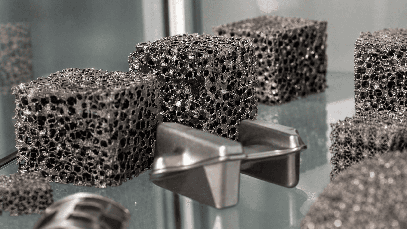
Table of contents
Share
When buying optical metrology equipment, one question is usually asked too early:
Which system should we buy?
The better question is:
What surface are we trying to measure, and what decision will the measurement support?
That distinction saves a lot of wasted time.
Additive manufacturing makes the selection harder because printed parts rarely present one neat measurement problem. A single component may have rough as-built surfaces, steep side walls, machined datums, polished functional faces, support marks, coating-sensitive areas and fine internal or external features.
No serious metrology discussion should pretend those surfaces are all the same.
For additive manufacturing, precision engineering, optics, medical devices, electronics and advanced materials research, the method behind the measurement is just as important as the instrument itself. Confocal microscopy, interferometry and focus variation each have strengths. The skill is knowing when to use each one.
Start with the surface, not the specification sheet
Resolution numbers are useful, but they do not tell the whole story.
A beautifully specified system can still be the wrong choice if the surface is too steep, too reflective, too rough, too smooth, too transparent, too fragile or too awkward to access.
Before comparing metrology systems, define the surface properly.
Is it rough or smooth?
Is it flat, curved, angled or recessed?
Is it reflective, transparent, coated or dark?
Is the feature micron-scale or larger?
Are we measuring roughness, waviness, form, step height, coating thickness, defects or process variation?
Is the measurement for R&D, incoming inspection, supplier approval, production QC or failure analysis?
These questions sound basic. They are not. They decide whether the measurement data will be useful or just decorative.
Why additive manufacturing needs careful metrology selection
Additive manufacturing gives engineers design freedom, but it also creates surface and form measurement challenges that conventional inspection methods do not always handle well.
Powder behaviour, melt pool stability, build angle, laser parameters, support strategy, material choice and post-processing can all influence the final surface.
A part may pass a visual check and still have surface texture that affects coating adhesion, wear, sealing, fatigue performance or cleaning behaviour. A roughness value may be useful, but it may not explain the full surface. A 3D topography map often gives a better view of what the process has actually produced.
With AM parts, the measurement task usually falls into one of four areas:
Process development
Comparing build parameters, materials, angles or post-processing methods.
Form verification
Checking whether the printed part matches a reference part or CAD model closely enough.
Surface texture analysis
Measuring roughness, waviness and areal parameters across functional surfaces.
Quality documentation
Creating repeatable, reportable evidence for engineering and quality decisions.
This is where optical 3D profilometry earns its place. It gives engineers surface data, not just images.
Focus Variation: for rough, steep and textured surfaces
Focus Variation is often the practical choice for rough, steep or highly textured surfaces.
The principle is straightforward. The system scans through different focus positions and builds a 3D surface from the points that come into sharp focus at each height.
For additive manufacturing, that is a useful tool. As-built AM surfaces often have strong texture, sharp height variation and angled features. Focus Variation can be a strong candidate when the surface has enough visual structure for the system to track focus reliably.
Typical applications include:
As-built metal AM surfaces
Steep printed features
Tooling and mould surfaces
Textured machined components
Rough functional surfaces
Micro-features with significant height variation
Focus Variation is not chosen because it sounds advanced. It is chosen when the surface geometry suits the method.
A common example is comparing surfaces printed at different build angles. The visible difference may be subtle, but the 3D surface data can show how the texture changes. That gives process engineers something more useful than a microscope image and a polite argument.
Confocal microscopy: for complex surfaces and fine structure
Confocal microscopy is useful when the surface has fine structure, mixed texture or optical complexity.
It captures the in-focus plane and rejects much of the out-of-focus light. The result is a cleaner measurement of the surface at each height level, which can then be built into a 3D representation.
Confocal is often a good option for parts that are not extremely rough, but are still too complex for a simple visual or 2D inspection approach.
Typical applications include:
Micro-structured surfaces
Precision machined features
Medical device surfaces
Electronics and micro-components
Reflective or mixed-finish materials
Research samples with small functional details
Confocal measurement sits in a useful middle ground. It can support detailed surface analysis across a broad range of engineering surfaces, particularly when fine lateral detail and 3D topography are both important.
For labs and manufacturers working with AM, this can be useful after post-processing, machining, polishing or coating, when the surface has moved from raw printed texture towards a more controlled functional finish.
Interferometry: for smooth, flat and highly finished surfaces
Interferometry is the method to consider when the surface is smooth, flat or highly finished, and very small height differences need to be measured.
It uses the interference of light to identify surface height variation. In simple terms, it is a very sensitive optical method for measuring fine vertical detail.
Interferometry is often used for:
Optical components
Polished surfaces
Wafers and microelectronics
Smooth post-processed surfaces
Step height measurement
Flat precision components
Thin films and coatings, depending on material and configuration
It is powerful, but it is not a universal answer.
Very rough AM surfaces, steep geometry or unstable measurement conditions may point towards a different technique. That is not a weakness. It is simply good metrology practice.
The method should serve the surface, not the other way around.
Why one additive part may need more than one method
This is the part many buying processes miss.
An additive manufactured component may not have one surface type. It may have five.
The as-built area may suit Focus Variation.
The machined datum may suit interferometry.
A fine micro-feature may suit confocal.
A coated surface may need a different measurement approach again.
A larger form comparison may require a separate 3D measurement method before the detailed surface work begins.
This is why Sensofar’s multi-technology approach is valuable. The S neox platform brings Confocal, Interferometry and Ai Focus Variation into one optical profilometer, allowing the measurement method to be selected according to the task.
For a laboratory, that gives flexibility.
For a quality department, it supports more repeatable workflows.
For additive manufacturing, it helps engineers follow the part through development, printing, finishing and inspection.
A practical selection guide
Use this as a starting point, not a final specification.
Choose Focus Variation when:
The surface is rough, steep or highly textured.
The part is as-built from additive manufacturing.
The geometry includes slopes, cavities or complex height changes.
Speed and surface coverage are important.
The surface has enough visible texture to support focus-based reconstruction.
Choose Confocal microscopy when:
The surface has fine detail or mixed texture.
The part includes micro-structures or small functional features.
Reflectivity or material behaviour makes simple imaging unreliable.
A clean 3D surface measurement is needed across a complex area.
The application is R&D, medical device inspection, electronics or precision manufacturing.
Choose Interferometry when:
The surface is smooth, polished or flat.
Fine vertical height differences are important.
The part is optical, wafer-like, coated or highly finished.
Step height, film-related measurement or surface finish control is required.
The measurement environment is stable enough for high-precision optical work.
Do not choose technology from a brochure
A brochure can tell you what a system can do. It cannot tell you how your part will behave under measurement.
That needs application work.
Representative samples should be tested. The difficult surfaces should be measured first. The reporting output should be checked. Operator workflow should be considered. If the measurement will support quality control, the process must be repeatable, not just impressive during a demonstration.
For production environments, the metrology question is rarely just “Can we measure it?”
Better questions are:
Can different operators get consistent results?
Can the measurement routine be locked down?
Can reports be generated in a usable format?
Can pass/fail decisions be supported?
Can the data be linked to quality or process records?
Can the system cope with the real part, not the perfect sample?
This is where equipment selection becomes engineering, not procurement.
Where AIET adds value
AIET Group supports manufacturers, laboratories and industrial teams with metrology systems that match real applications rather than catalogue assumptions.
For Sensofar optical metrology, that means helping define the part, surface, measurement objective, technology route and workflow before a system is specified.
The important work is often done before the purchase order:
Understanding the measurement problem
Reviewing representative samples
Identifying the right optical method
Checking surface accessibility
Defining reporting needs
Considering production or laboratory workflow
Supporting local demonstration and technical discussion
Connecting the measurement result to the quality decision
For UAE and GCC organisations investing in additive manufacturing, aerospace, defence, energy, medical devices, electronics, precision engineering or research capability, local support is not a small detail. It affects how quickly a project moves from interest to useful measurement.
A metrology system should not become expensive furniture. It should help engineers make better decisions.
Common mistakes when selecting optical metrology for AM
The first mistake is treating all roughness measurement as the same job.
A stylus roughness value, a microscope image and a 3D optical surface map can answer different questions. Sometimes they complement each other. Sometimes one is clearly the better route.
The second mistake is choosing based only on maximum resolution.
Resolution is important, but surface type, field of view, slope capability, reflectivity, software analysis, repeatability and reporting may be more important for the actual inspection task.
The third mistake is testing only the easiest sample.
Measure the awkward part. The steep surface. The dull surface. The reflective patch. The post-processed feature. The area where quality arguments usually start.
That is where the right system proves itself.
FAQ
What is the best optical metrology method for additive manufacturing?
There is no single best method. Rough as-built AM surfaces often suit Focus Variation. Complex or mixed surfaces may suit confocal microscopy. Smooth post-processed surfaces may suit interferometry.
Is Focus Variation better than confocal microscopy?
Not generally. Focus Variation is often stronger on rough, steep and textured surfaces. Confocal microscopy is often better for complex surfaces where fine detail and optical sectioning are useful.
When should interferometry be used?
Interferometry is usually selected for smooth, flat or highly finished surfaces where very small vertical height differences need to be measured.
Can one optical profilometer measure different surface types?
Yes, if the platform includes more than one optical measurement technology. Sensofar S Neox combines Confocal, Interferometry and Ai Focus Variation, which gives engineers more flexibility across different surfaces and applications.
Should additive manufacturing samples be tested before choosing a system?
Yes. Sample testing is one of the best ways to avoid buying a metrology system that looks suitable on paper but struggles with the real surface.
Is optical metrology only for laboratories?
No. Optical metrology is widely used in R&D and laboratory environments, but it can also support quality control, process development, production inspection and supplier qualification when the workflow is properly defined.
Speak to AIET Group
If you are comparing optical metrology technologies for additive manufacturing, surface texture measurement, R&D or production quality control, speak to AIET Group.
We can review the application, discuss representative samples and help identify whether Confocal, Interferometry, Focus Variation or another measurement approach is the right route.


