
Surface Texture vs Roughness: A Practical Guide for Additive Manufacturing

Matt Wilton
Director

Table of contents
Share
The phrase “surface roughness” gets used for almost everything.
A part feels rough. A coating does not sit properly. A seal does not behave as expected. A printed surface looks inconsistent under magnification. The usual response is to ask for a roughness measurement.
That may be the right starting point. It is not always the whole answer.
For additive manufacturing, precision machining, coating, tooling and micro-scale production, the surface needs to be understood in three dimensions:
Not just seen. Not just described. Measured.
Sensofar describes surface texture as the irregularities and variations on a material’s surface that influence function, appearance and durability. It also separates roughness from waviness, which is a useful distinction when a surface has both fine detail and broader shape variation.
What is surface texture?
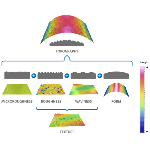
Surface texture is the full pattern of height changes across a surface.
That includes the fine peaks and valleys, the broader waves, the lay or direction of the surface, and the local features caused by the manufacturing process.
On a 3D printed metal part, surface texture may come from powder size, melt pool behaviour, laser parameters, build orientation, support removal, heat treatment, machining, blasting, polishing or coating. Two surfaces can look similar to the eye but behave differently in use.
A proper measurement gives the engineer numbers, maps and profiles that can be compared. That is much more useful than “looks acceptable”.
Roughness is only one part of the surface
Roughness usually refers to the fine irregularities on the surface. These features can influence friction, wear, adhesion, sealing, fatigue behaviour and how a part accepts a coating.
Waviness refers to larger undulations. These can come from machine behaviour, vibration, heat effects, process instability or form error. A surface can have acceptable roughness but poor waviness. The reverse can also be true.
That is why surface texture is the better umbrella term. It allows the measurement discussion to include roughness, waviness, form, filtering and the correct parameter for the job.
Sensofar’s surface texture guidance puts the process into three stages: measuring, filtering and analysis. It also references ISO 25178 and ISO 21920 for areal and profile surface texture analysis.
Why additive manufacturing makes this more complicated
Additive manufacturing gives engineers design freedom that traditional machining cannot always match. Internal channels, lattice structures, lightweight forms and complex geometries are all part of the attraction.
The trade-off is measurement difficulty.
Printed surfaces are often directional, layered, partially fused, reflective in some areas and rough in others. The same part may have upward-facing surfaces, downward-facing surfaces, side walls, support-contact areas and post-processed zones. A single roughness number rarely explains all of that.
There are several challenges around AM parts, including limited standardisation, difficulty controlling dimensions and surface properties, and the frequent need for post-processing.
For quality teams, this creates a very practical question:
Are we measuring the surface in a way that reflects how the part will be used?
As-built and post-processed surfaces are different problems
The “as-built” surface is the surface straight from the additive process. It may be useful for research, process development or incoming inspection before finishing.
The post-processed surface is the one after machining, polishing, blasting, heat treatment or coating. This is often closer to the functional surface the customer actually cares about.
A sensible metrology approach may need to compare both. For example:
A medical or aerospace component may need texture data before and after finishing.
A coated part may need surface information before coating to understand adhesion risk.
A tooling insert may need repeated measurement to track wear.
A research lab may need to compare build angles, machine parameters or materials.
Sensofar’s non-contact 3D optical metrology can be used to characterise form and texture on AM parts, including as-built and post-processed samples.
What 3D optical metrology adds
A microscope image can show the surface. A 3D optical profilometer can measure it.
A 3D optical profilometer captures height information across an area. The result is a 3D topography map, not just a picture. Engineers can then analyse roughness, waviness, step height, profile, pits, peaks, micro-geometry and local features.
For delicate, small or high-value parts, non-contact measurement is also useful because the instrument does not drag a stylus across the surface. That does not mean optical measurement replaces every contact method. It means it gives engineers a powerful option when surface detail, measurement speed and 3D data are required.
AIET’s Sensofar page describes optical surface metrology as a way to measure micro- and nano-scale surface structure without physical contact, producing 3D topography data for roughness, thickness, defects and micro-geometry.
Sensofar for surface texture measurement
Sensofar optical metrology systems are designed to turn surface detail into quantitative data.
This is important for manufacturers and laboratories working with additive manufacturing, precision engineering, optics, medical devices, electronics, coatings, advanced materials and R&D. The common thread is not the sector. It is the need to understand the surface properly before making a quality, design or process decision.
Sensofar’s S Neox unique platform combines optical metrology technologies such as confocal microscopy, interferometry and AI Focus Variation within the same system, giving engineers more flexibility across different surface types.
For additive manufacturing, that flexibility is useful because one part can present several measurement problems at once: rough as-built areas, smoother machined faces, angled surfaces, coated areas and small features.
Selecting the right optical profilimeter
A metrology system should not be selected from a brochure alone.
The right approach depends on the part, material, surface condition, tolerance, production environment, reporting requirement and operator workflow. A research lab does not always need the same setup as a production QC department. A one-off development project does not always need the same automation as a repeat inspection cell.
AIET Group supports optical, tactile, 2D/3D surface measurement, profilometry, non-contact dimensional inspection and high-accuracy QC systems for production and lab environments. AIET’s metrology work is positioned around practical deployment, including surface and finish measurement, form, roughness, waviness, traceability and industrial integration.
For organisations developing or qualifying 3D printed parts, AIET can help frame the measurement problem before the equipment decision is made.
Practical questions before measuring a 3D printed surface
Before choosing a surface measurement method, ask:
What does the surface need to do?
Is the part being measured as-built, post-processed or both?
Are we checking roughness, waviness, form, defects or coating-related behaviour?
Do we need a 2D profile, a 3D areal measurement or both?
Which areas of the part are functional?
Will this be used in R&D, inspection, supplier qualification or production QC?
Does the measurement need to be repeated by different operators?
Do results need to be linked to reports, traceability or process data?
These questions are not academic. They decide whether the measurement will be useful.
Speak with AIET
If you are reviewing surface texture measurement, additive manufacturing inspection or optical profilometry for production or laboratory use, contact AIET Group to discuss the application.
FAQ
What is the difference between surface texture and surface roughness?
Surface texture is the broader term. It includes roughness, waviness and other surface features. Roughness refers to the finer irregularities on the surface.
Why is surface roughness important for 3D printed parts?
Roughness can affect friction, coating adhesion, wear, sealing, cleaning behaviour and fatigue performance. It can also reveal process variation between materials, build angles or machine settings.
Can optical profilometers measure rough 3D printed surfaces?
Yes, depending on the surface, geometry and optical technique used. Rough, steep or highly textured surfaces may require a different approach from smooth, flat or reflective surfaces.
Is one roughness number enough?
Sometimes, but often not. Additive parts may need areal 3D measurement, filtering and multiple parameters to properly describe the surface.
Who should consider Sensofar surface metrology?
Manufacturers, R&D teams, universities and quality departments working with additive manufacturing, precision parts, coatings, micro-features, medical devices, optics, electronics or advanced materials.


